.png)
Robot Dog
Custom 12DOF large form factor quadrupedal robot
Skills
Project Overview
This robot dog is a custom designed 12 degree of freedom robotic quadruped featuring a custom cycloidal and capstan gearbox. The final build will weigh roughly 80 pounds and takes up a 2ft x 3ft envelope of space. This robot was designed to be a large form factor quadrupedal robot for a low price that is easily modifiable for further research or projects.
Design Overview
This design was made fully in Onshape over the course of roughly 100 hours of cad and numerous iteratons. It is split into 4 distinct parts - the frame, leg assemblies, electronics, and firmware. This design used as many parts that could be sponsored or were already on hand as possible to keep costs down. The final BOM stands at around 5k, but due to sponsorships and already having items the final cost came out to roughly 1k. I also put a huge emphasis on printing as much as I could, which is why the actuators, capstan, and some structural parts came out printed.
The Frame
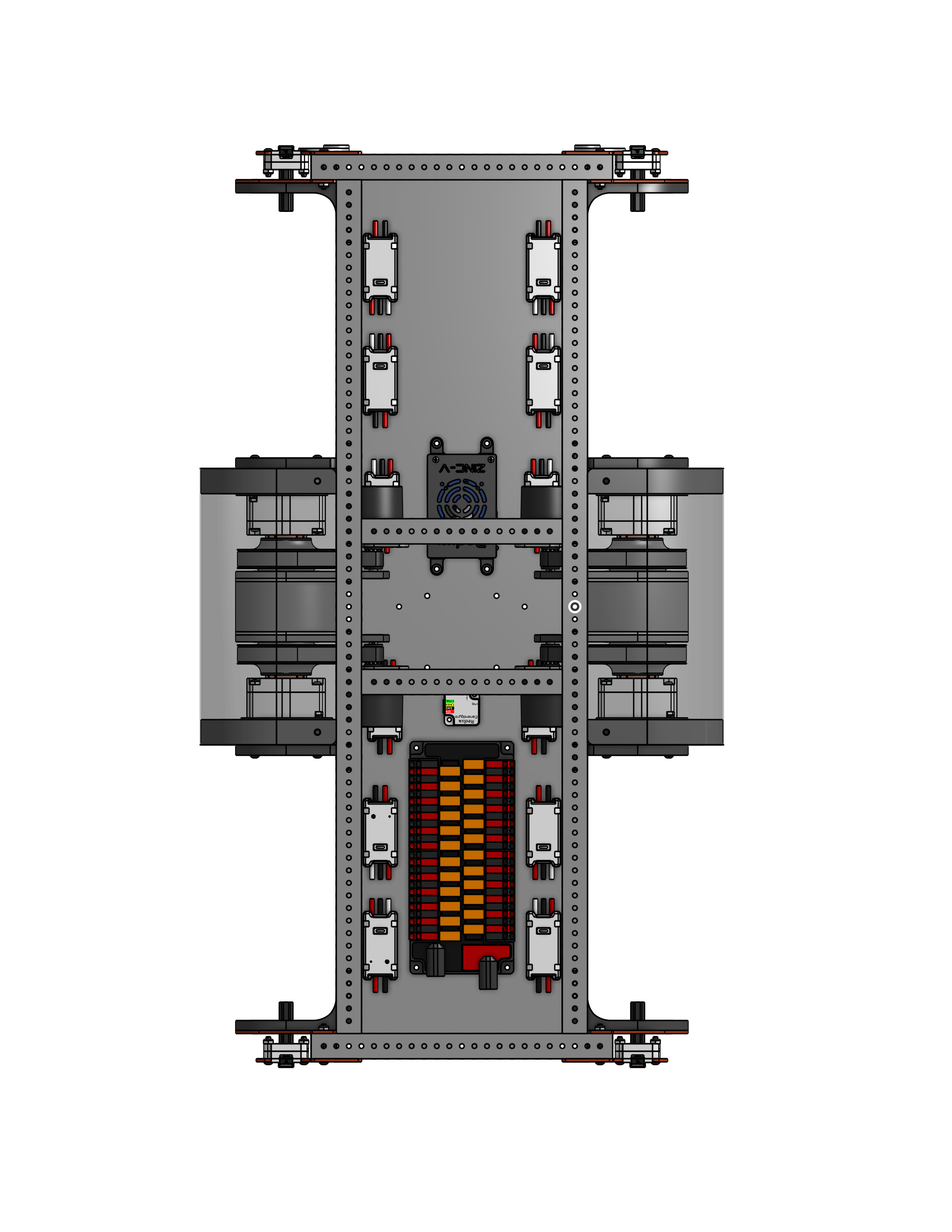
The frame utilize a 1x1 tube and gusset construction to create a lightweight, robust frame. It holes the electronics and mounts for the four leg assemblies as well as the motors and gearboxes to rotate said legs. It uses printed mounts combined with some aluminum plates for strength to mount the 4 legs and the gearbox assemblies that actually rotate them.
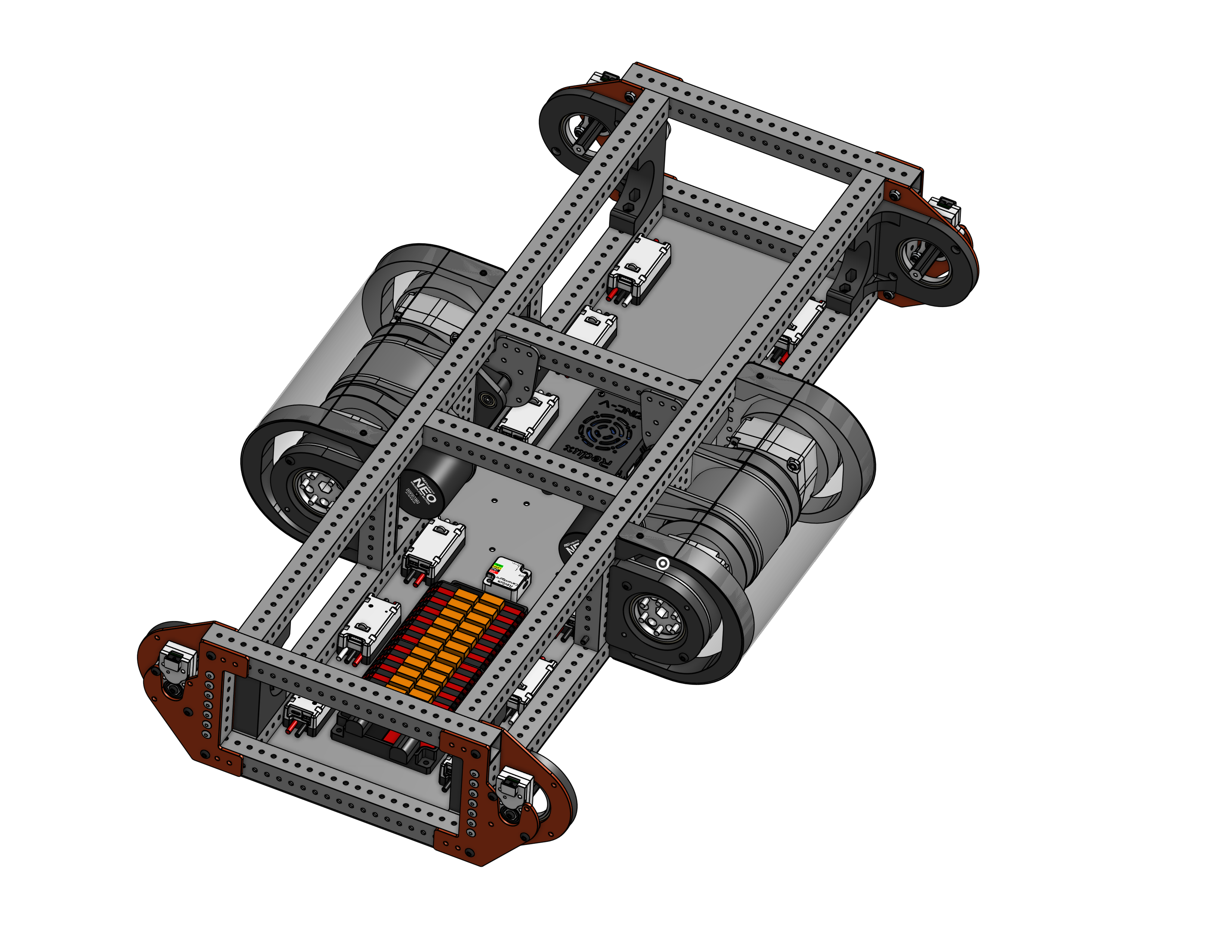
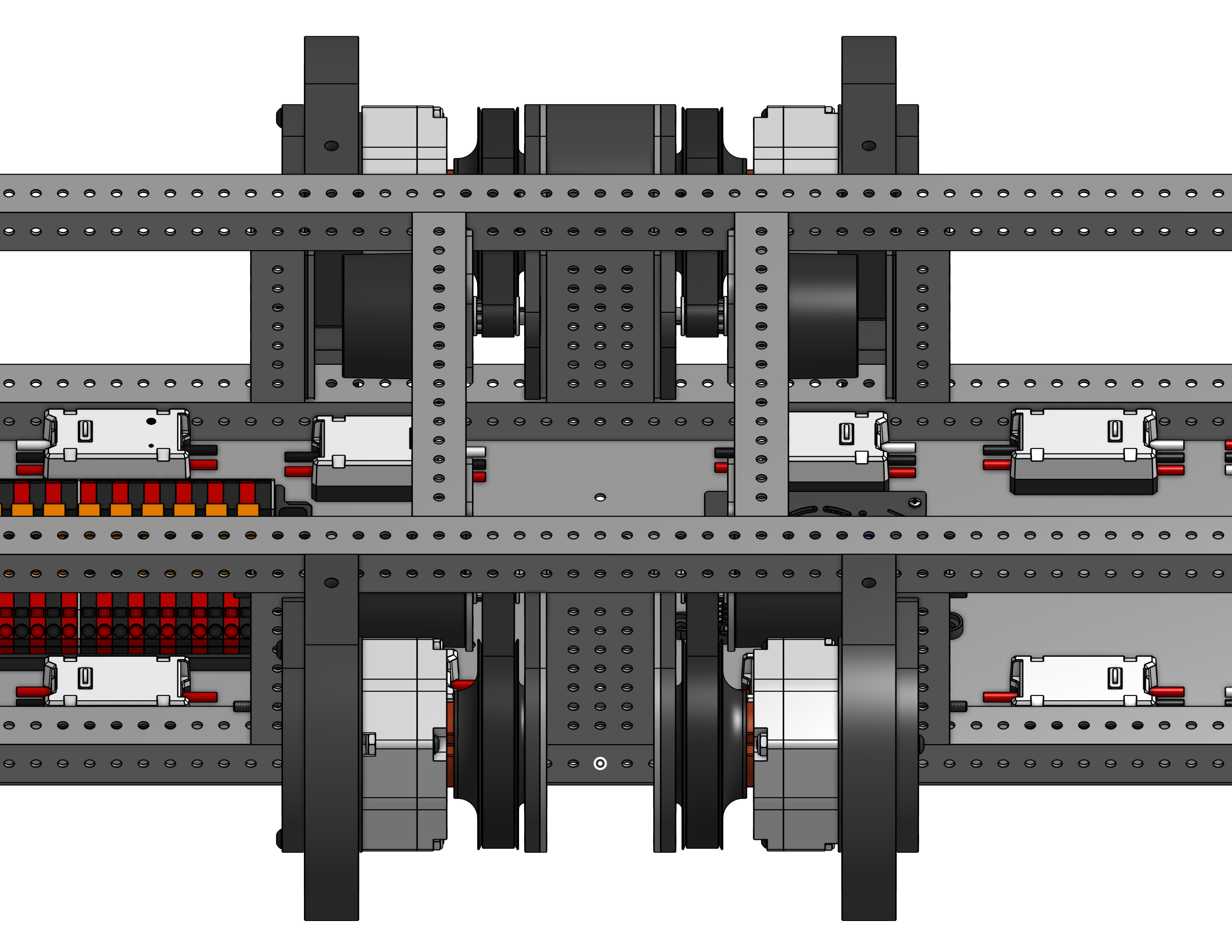
For the shoulder rotation, there is a Neo v1.1 BLDC that drives a 3:1 belt reduction that goes into the 20:1 custom cycloidal for a total reduction of 60:1 to pivot the shoulder side to side. This assembly is mirrored on both sides for a small compact design.
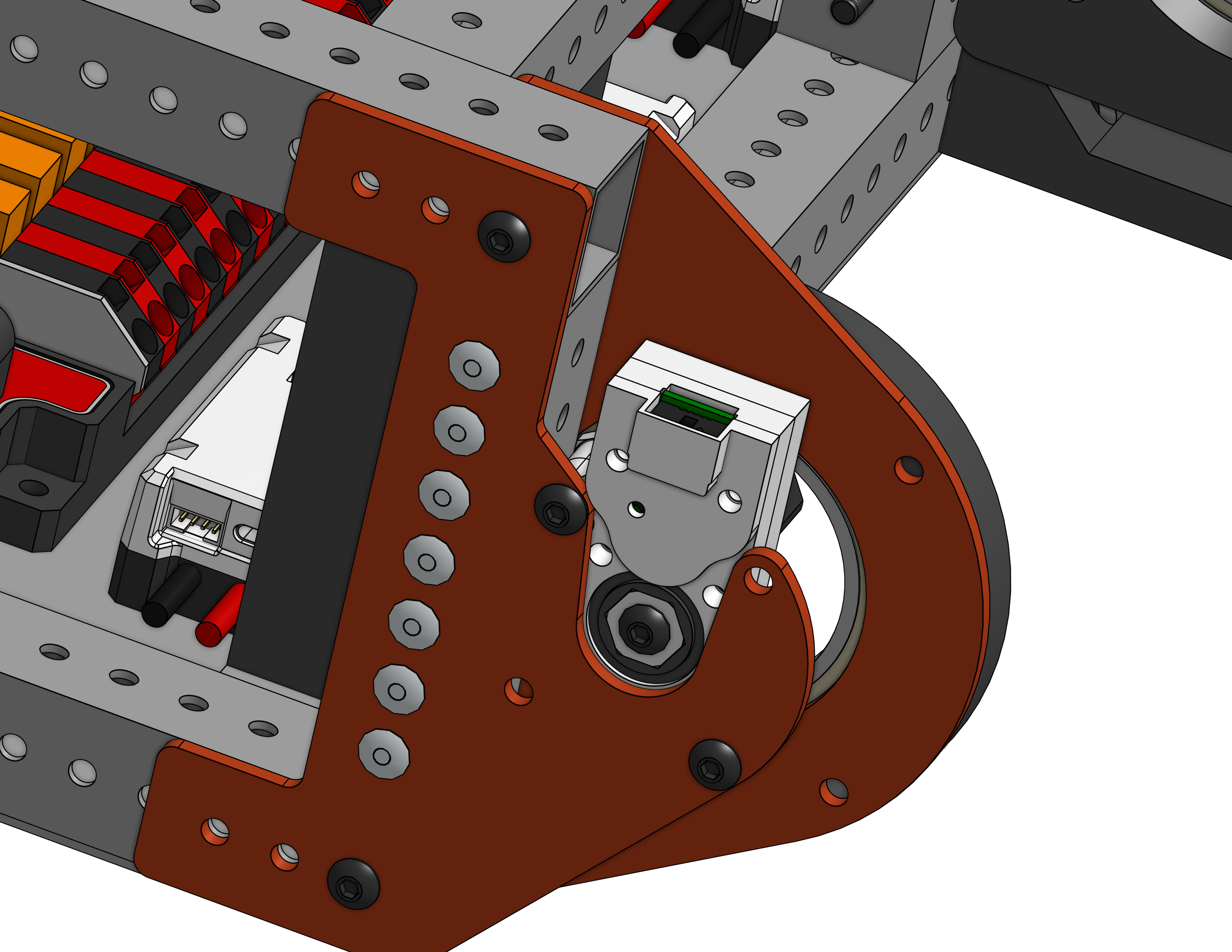
Finally, there is a built in Redux Throughbore Magnetic Encoder on each of the shoulder pivots to accurately track the position of each joint down to the hundredth of a degree. These encoders connect back directly to the Spark Max motor controller for instant feedback with the individual motor.
The Leg
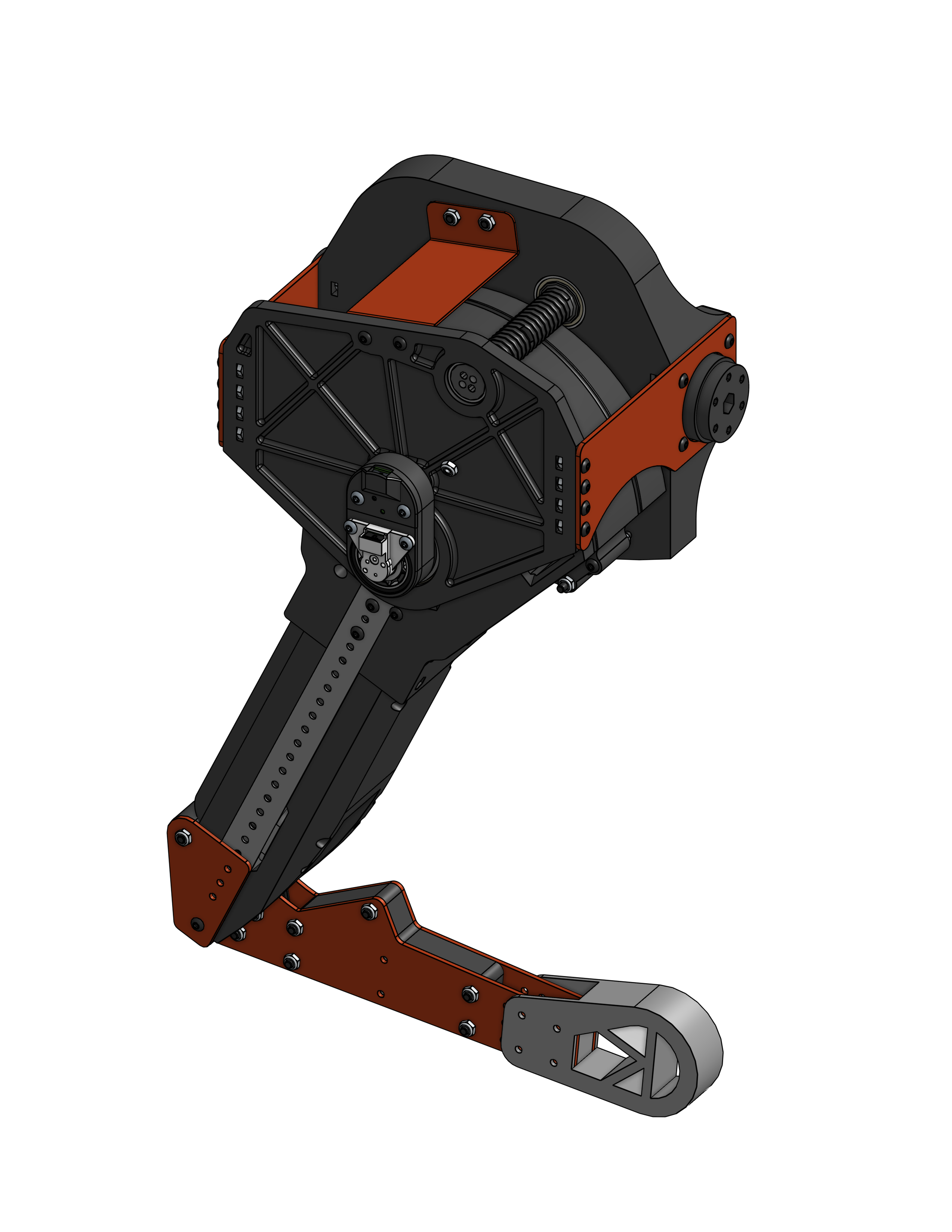
There are 4 leg assemblies, with the right and left sides being mirror images of each other.
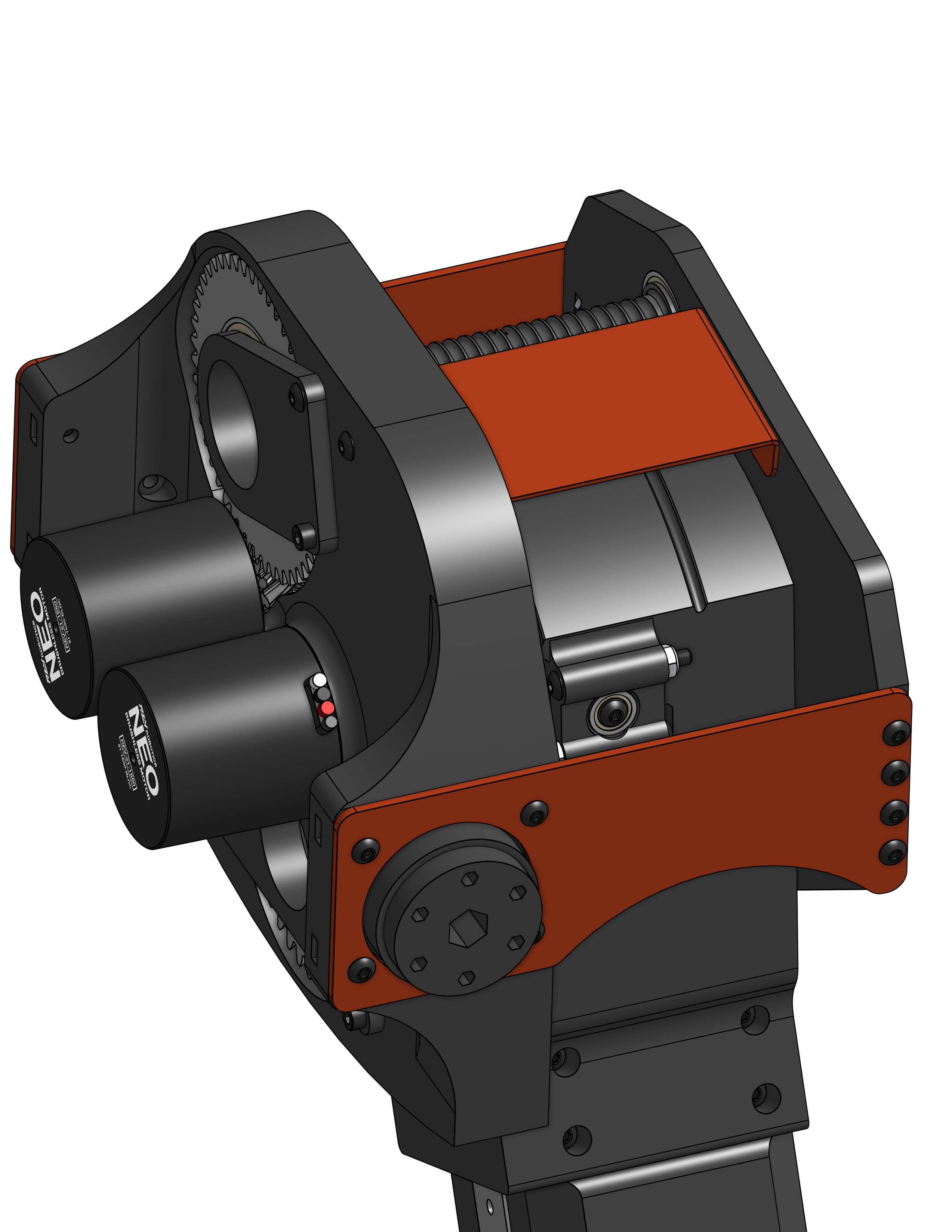
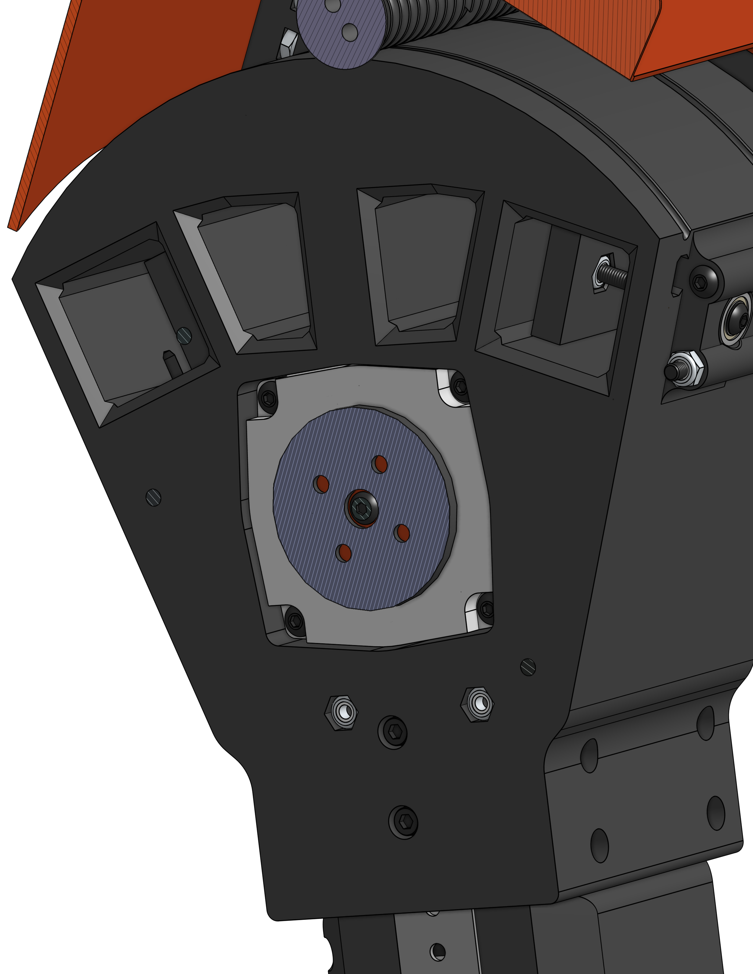
The leg utilizes a coaxial power setup for the knee, allowing both motors to remain on the frame, making wiring extremely easy. There is a captive cycloidal gearbox to create a large enough reduction for the knee.
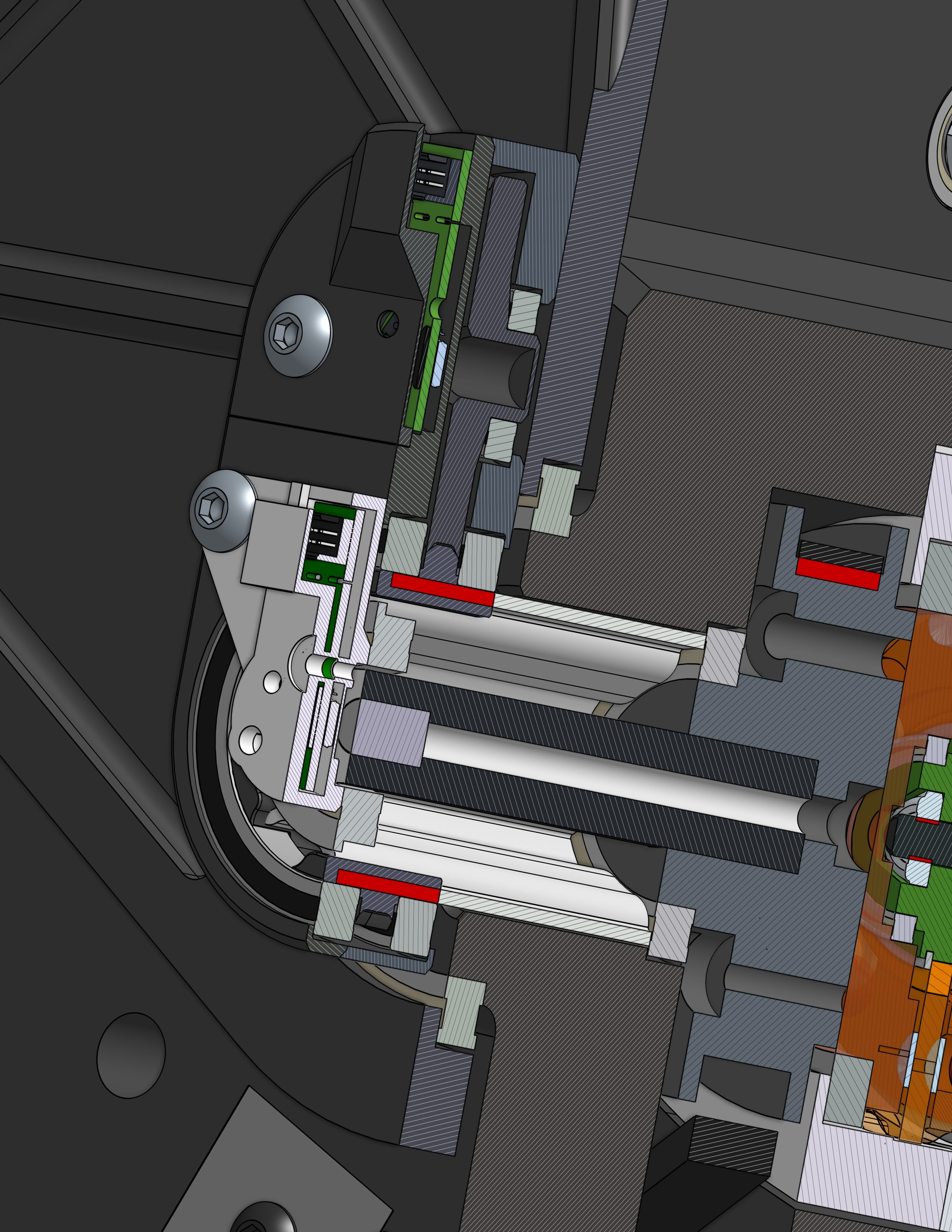
There is also a coaxial encoder setup for the individual joints. Using a clever stack of bearings, different types of shafts, and two different encoder housings, I created a compact setup that individually reads the two joint positions.
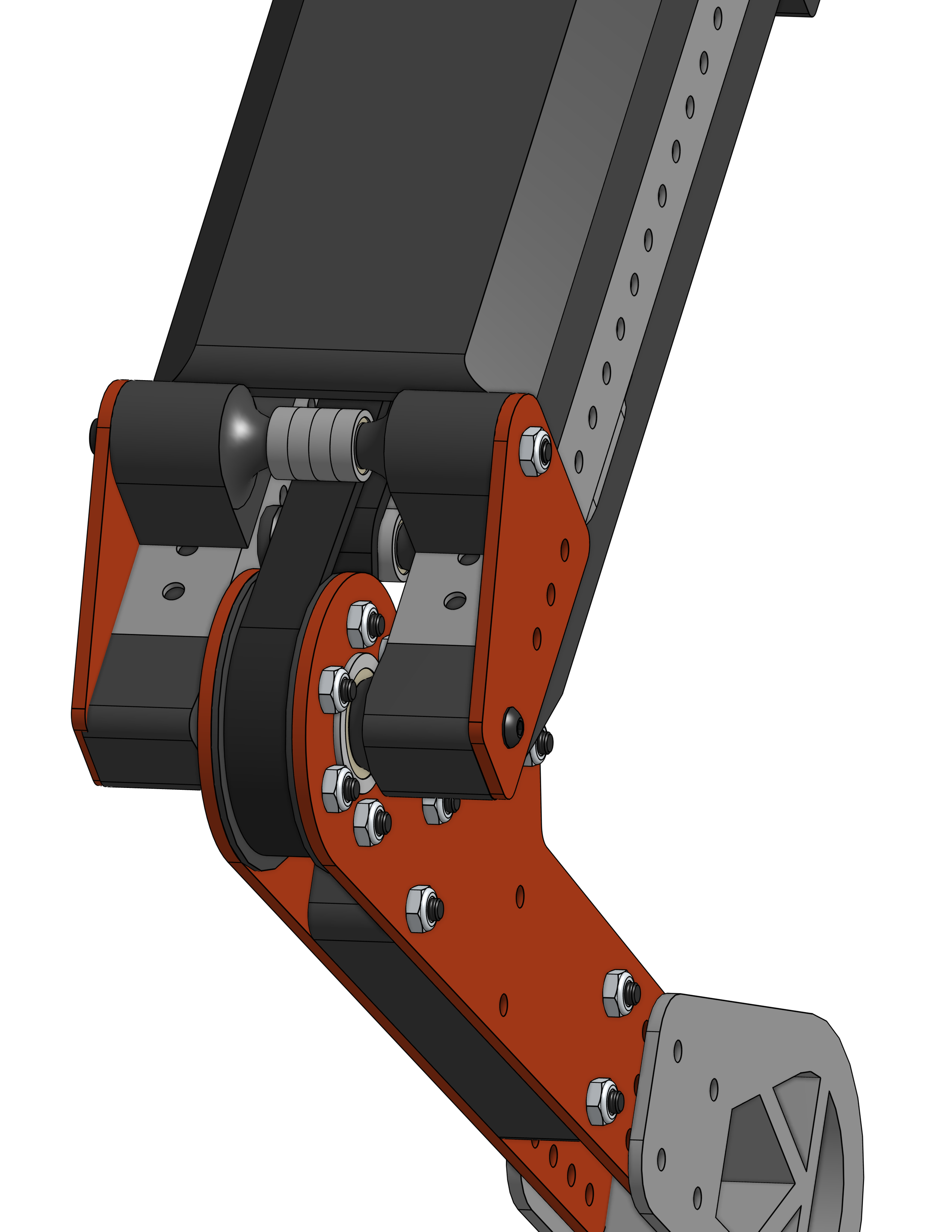
The knee is belt driven for low weight and backlash. It has two tensioners to keep proper tension on the belt. The knee pulley and subsequent lower leg segment are one set of sandwiched plates that connects up to the custom grippy foot.
Electronics
The electronics stack has a RPI5 at the top running ROS and communicating with the controller via wifi. For power, the robot is driven by 2 20V drill batteries in parallel for longer run time. This system connects to a CTRE PDP 2.0 to distribute the power, with the motor controllers directly plugging into the distribution board while the RPI and other peripherals have their power go through a buck converter to regulate it down to 5V and 12V first. Additionally, there is a Redux Boron gyro in the middle of the robot giving accurate measurements of the robot’s angle as it moves in all axis.
Firmware
The firmware is ROS2 controlling the robot. Gazebo simulation was used to test the robot in software before running code on the real bot. More details to come.