Hydra
Custom 5 head toolchanger 3D-Printer - Fully custom tool changing mechanism integrated with COTS printer parts
Skills
Project Overview
Hydra is a fully custom designed 5 toolhead CoreXY gantry 3D printer. It contains a large 310 mm x 310 mm x 240 mm build volume, automatic toolhead changes, auto z leveling, and a custom slicer profile. Designed fully in Onshape in my last year of high school over 100 hours of in CAD development, this printer was the first custom printer that made it out of the CAD stage. I’ve always wanted to design a toolchanger 3D printer, so with some free time before college, I took the leap.
Design Overview
Multi color and multi material printing has long been a passion of mine. This printer takes the best of both worlds, allowing for up to five different colors and/or materials to be used in one print. I made it my goal to fully design this printer in Onshape, allowing me to properly budget space and ensure that everything gets assembled smoothly.
.png)
Frame and Electronics
The frame of Hydra uses 2020 extrusion combined with 3D printed L brackets and CNC aluminum gussets to create a strong robust frame. It was designed to accomodate the COTS build plate and electronics box in the back while also being optomized to neat measurements to make manufacturing easier.
I used 2020 extrusion for a few reasons:
- interfaces well with the MGN9 rails I wanted to use
- easy to work with and build a platform off of
- extrusion is easier to machine over sheet metal or round tube
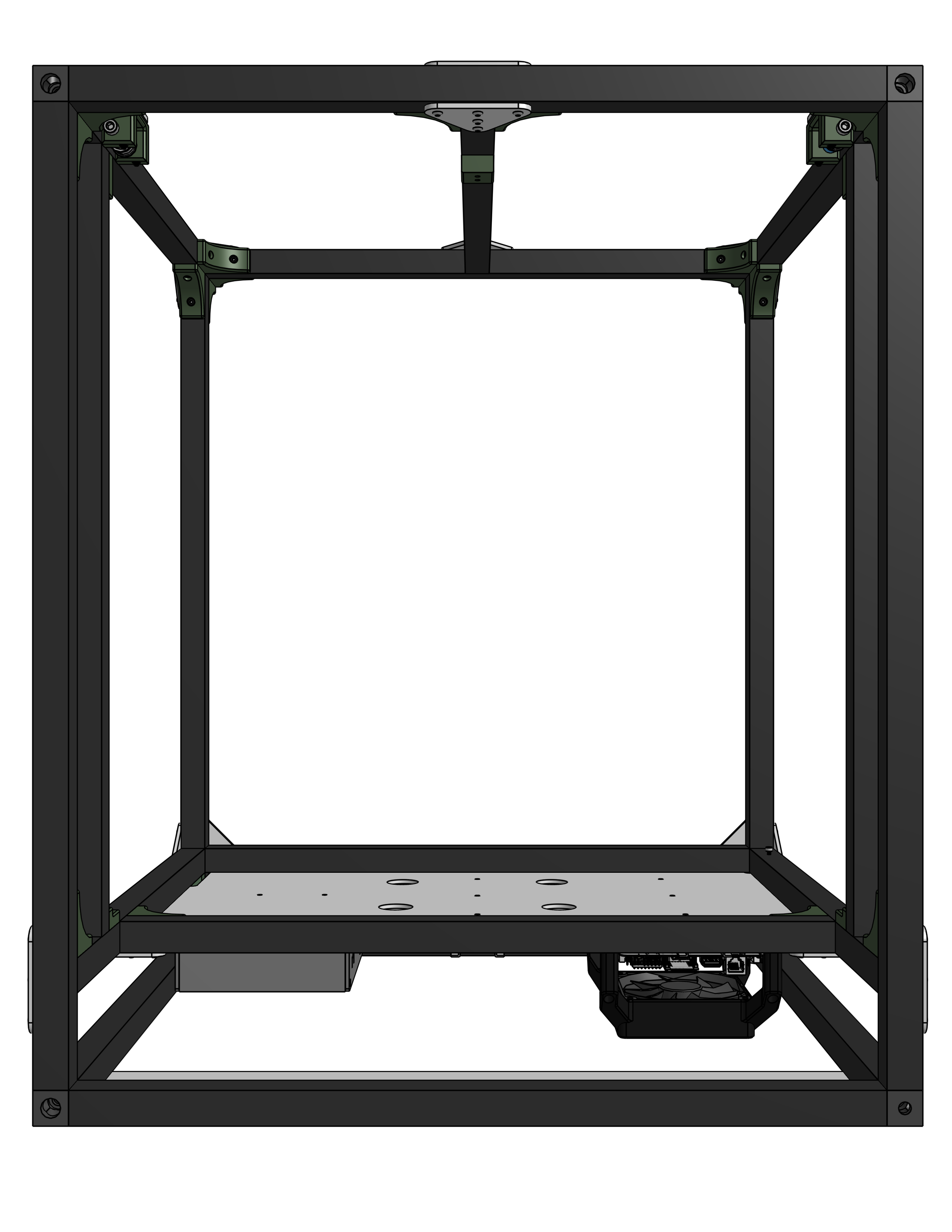
The frame ended up being just under 20” x 24”, being just big enough to fit the entire 310 mm x 310mm build plate space while still being able to fit through a door easily.
I went with electronics on the back of the printer for:
- ease of access
- more workable space
- I already had to extend the printer out that way for the toolhead docks
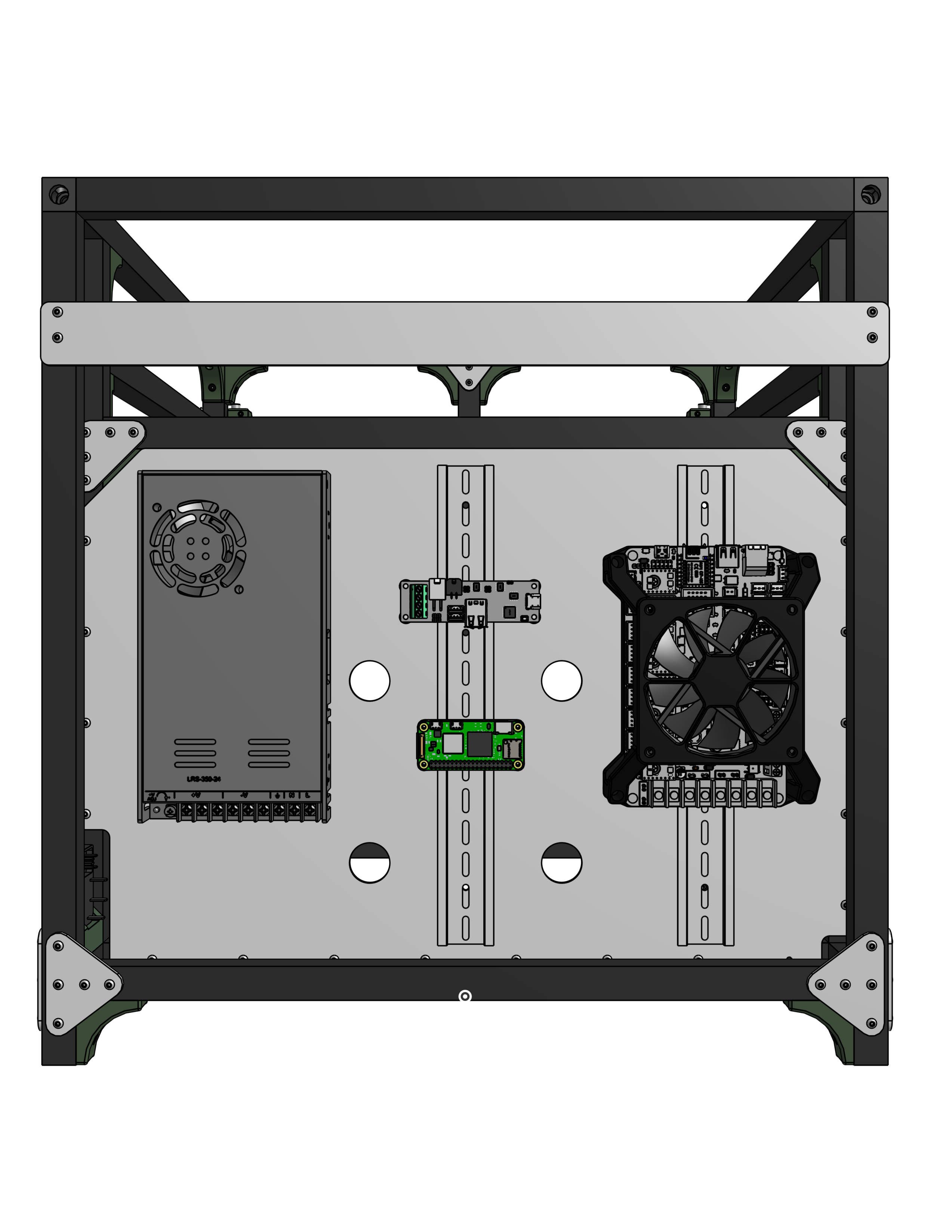
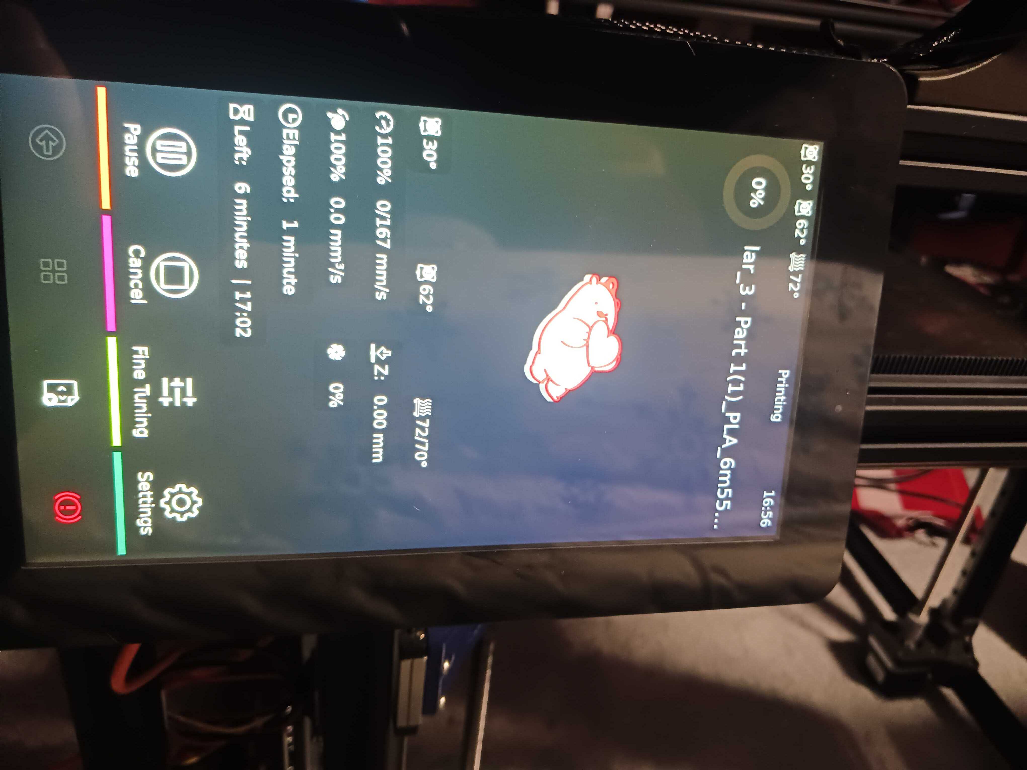
I am using the Big Tree Tech (BTT) Octopus Pro v1.1 for my mainboard, a Meanwell LRS-350-24 Power Supply, and a Raspberry Pi 5 for my coprocessor. Note that while the CAD contains a Pi 0 2W, I upgraded to a Pi 5 to install a touchscreen interface, shown below. I am also using the BTT U2C Can converter to communicate with my 5 toolheads over CAN protocol. These were all mounted on a piece of lasercut acrylic that also isolated the build chamber from the electronics to prevent overheating.
Toolhead + Toolchanger Design
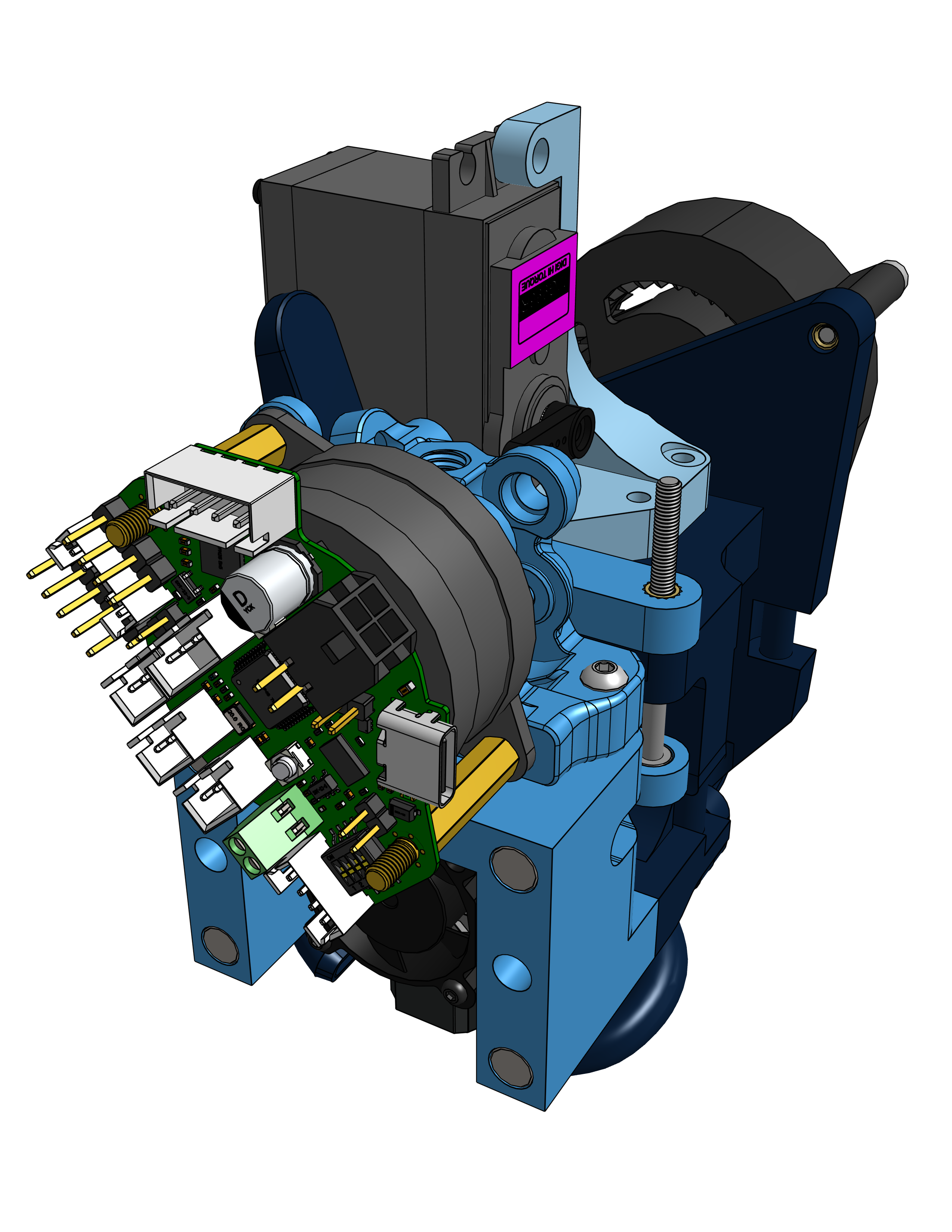
The toolhead and toolchanger design was custom designed by me in order to create a simple, reliable mechanism without needing a flying gantry (toolhead on a z axis).
Looking at the mechanism, it utilizes a sprung servo system that uses a servo to open the latch and a spring to close it and keep the toolhead on the gantry. It also uses a pair of magnets and COTS nozzles to align the toolhead to the holder and keep it aligned.
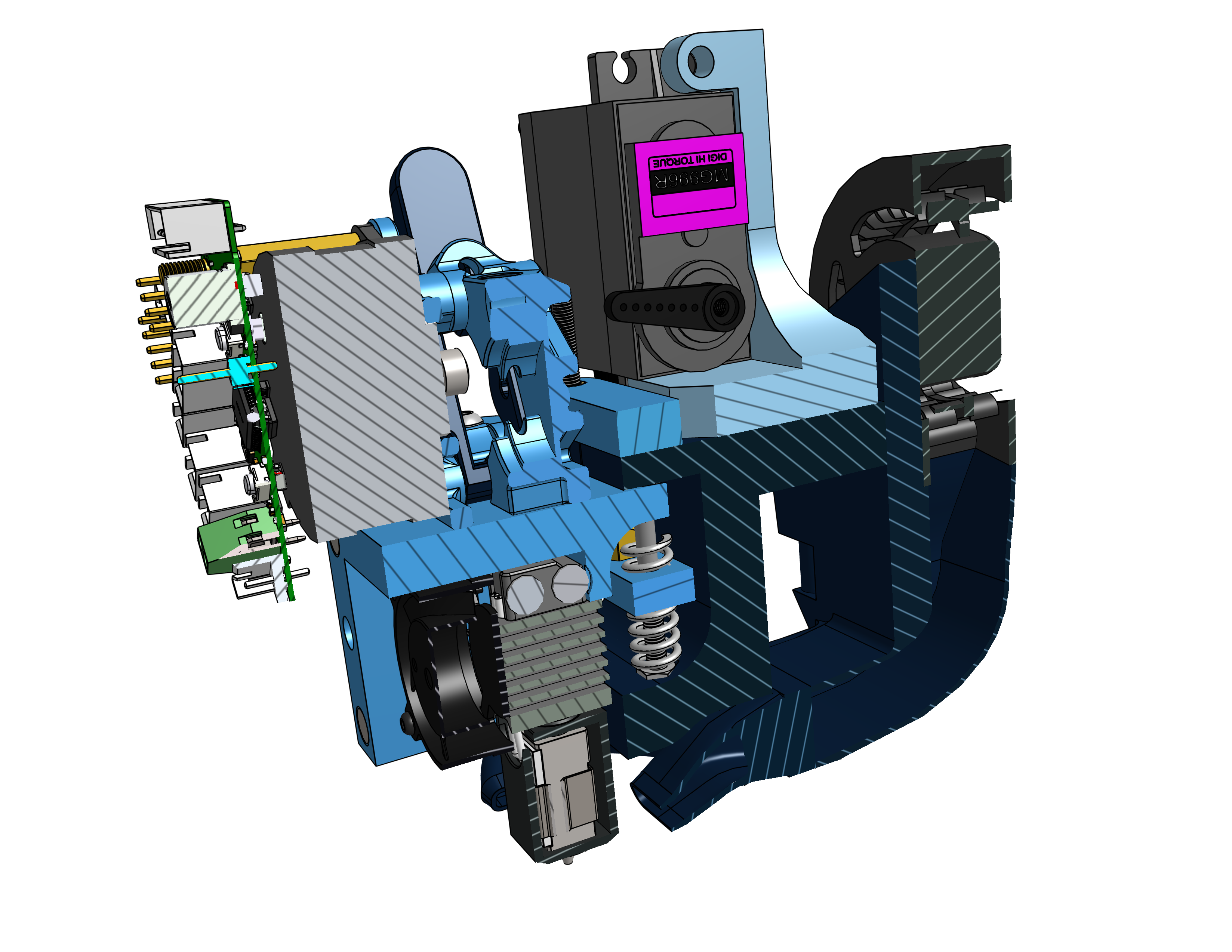
The toolhead itself was designed around a few core concepts:
- cost
- ease of assembly
- performance
- horizontal footprint
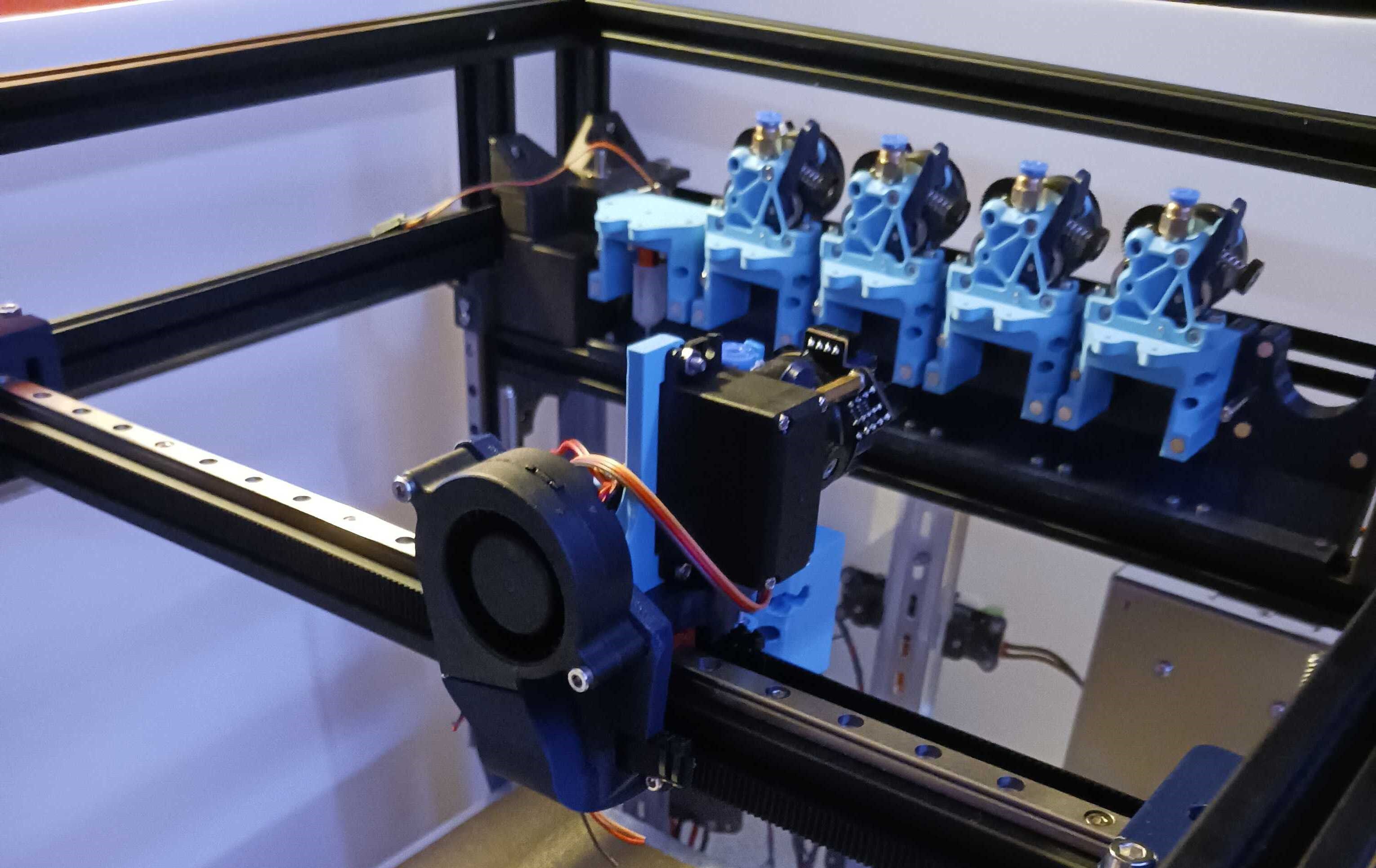
- futureproofing With these constraints, I used the ProtoXtruder 2.0 combined with the Bambu Labs hotend and the BTT EBB 36 toolhead board, which allowed me to create a mostly printed, modular toolhead that had a horizontal footprint of 2.1 inches. This allowed me to fit all 5 toolheads into my limited space on the printer. I went with direct drive to increase the number of different filaments I could reliably print with over bowden drive, along with being able to mount the toolhead board to the motor of the extruder, leading to better packaging.
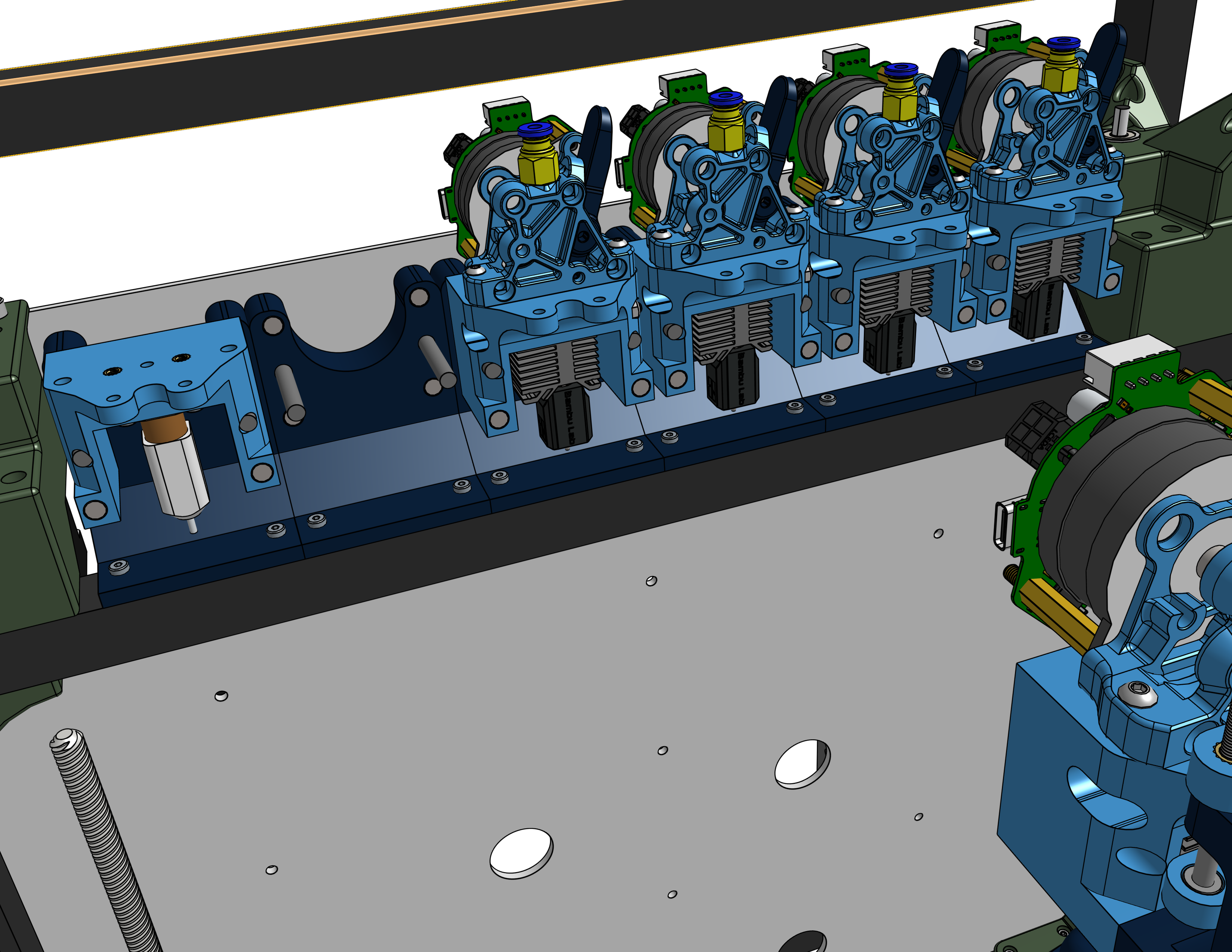
Motion System - X, Y, and Z
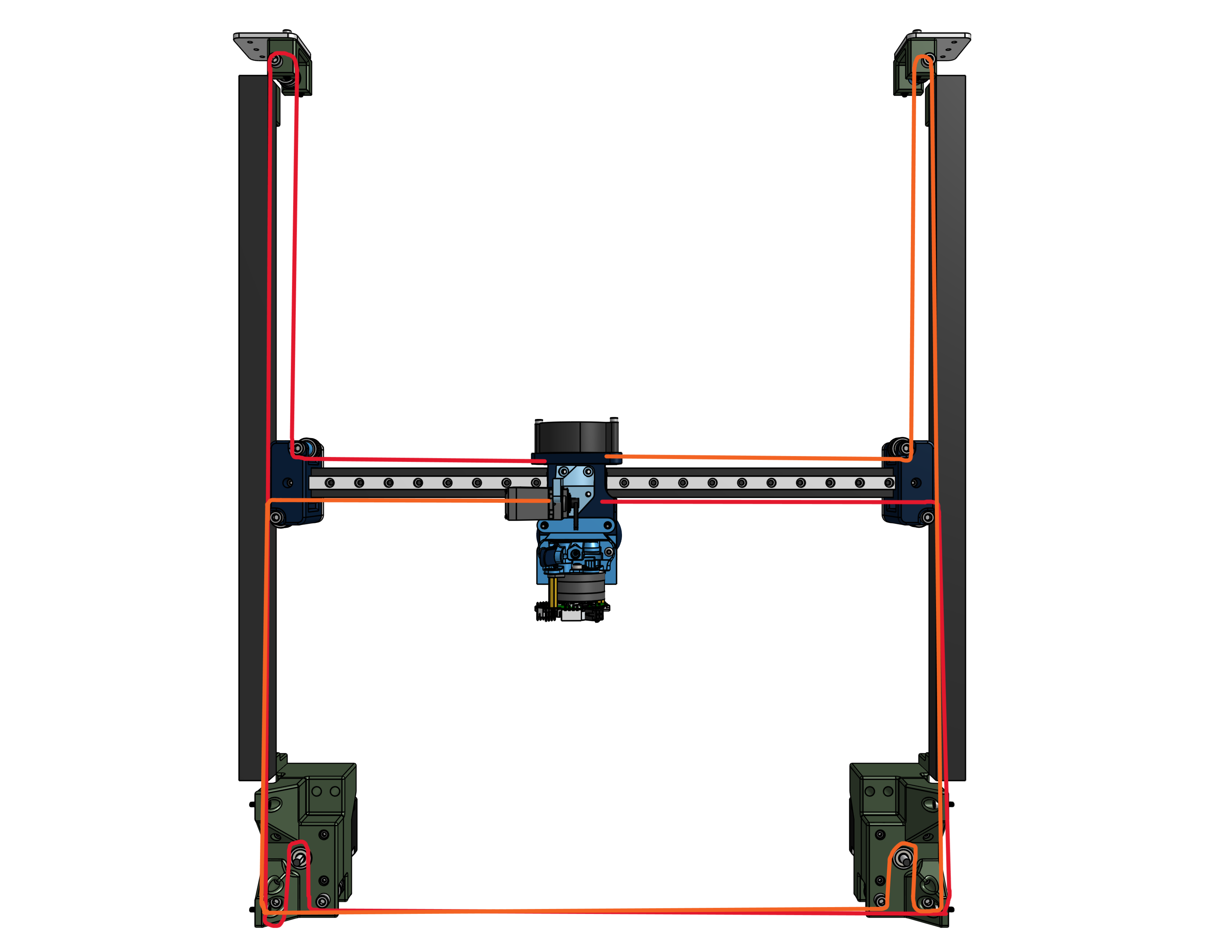
I utilized a belt driven CoreXY motion system for my gantry, driven by two Nema 17 stepper motors and GT2 Belts on MGN9 linear rails, chosen for a combination of strength, speed, and cost.
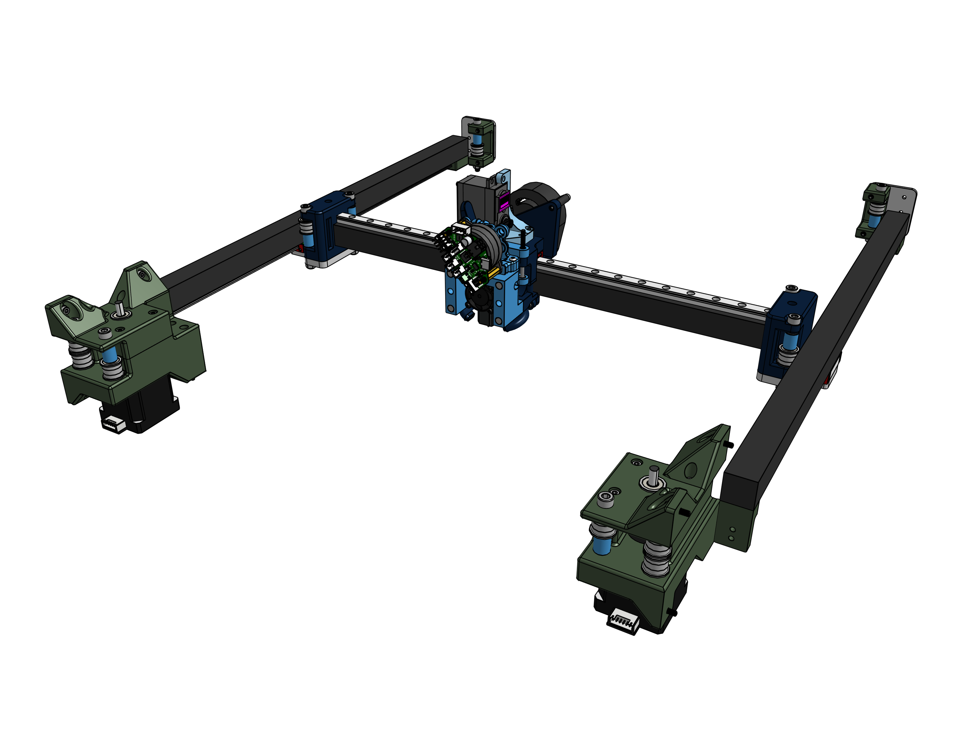
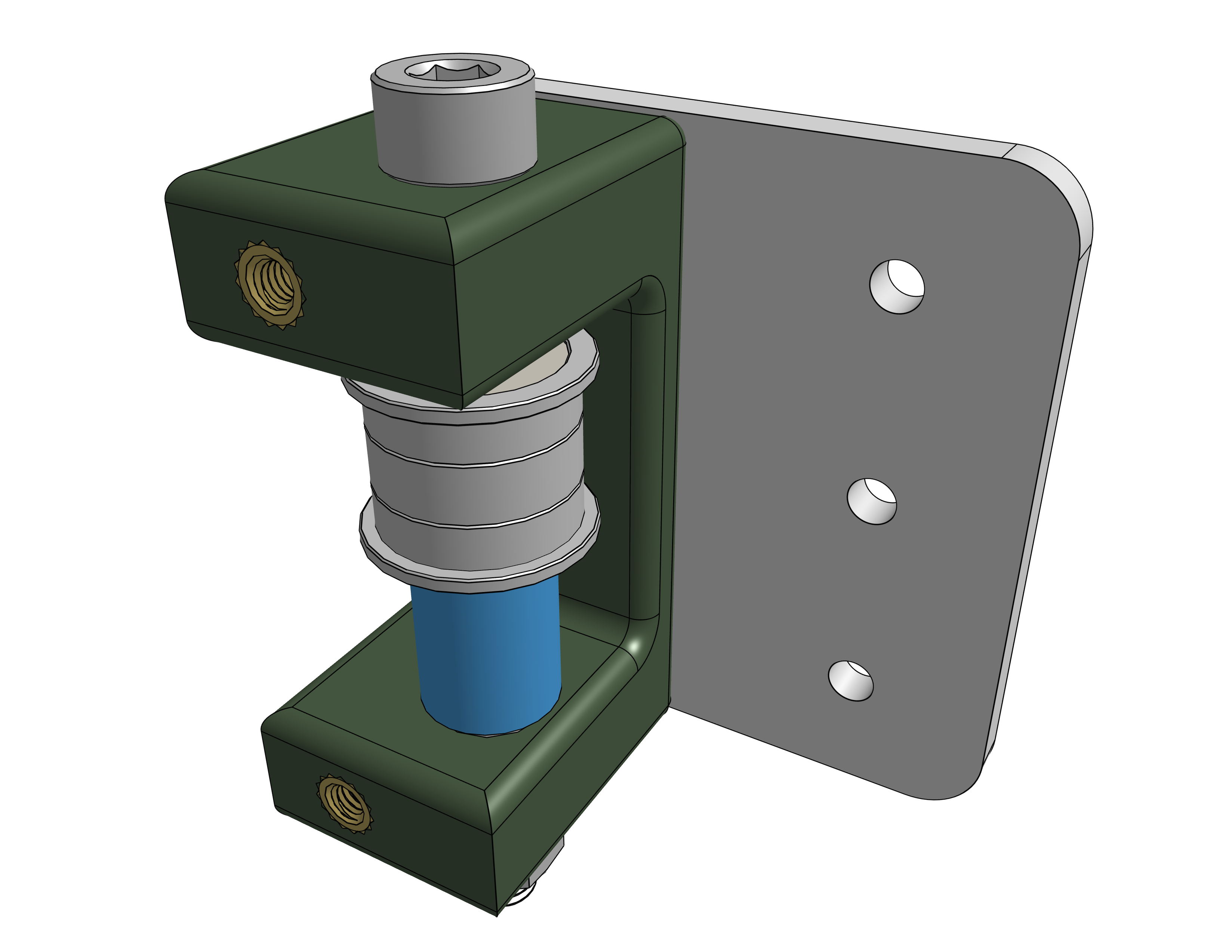
The motor mounts were a two part system that build in the idlers to redirect the belt in the direction I want along with housing an additional bearing to keep the shaft from being cantilevered by the belt.
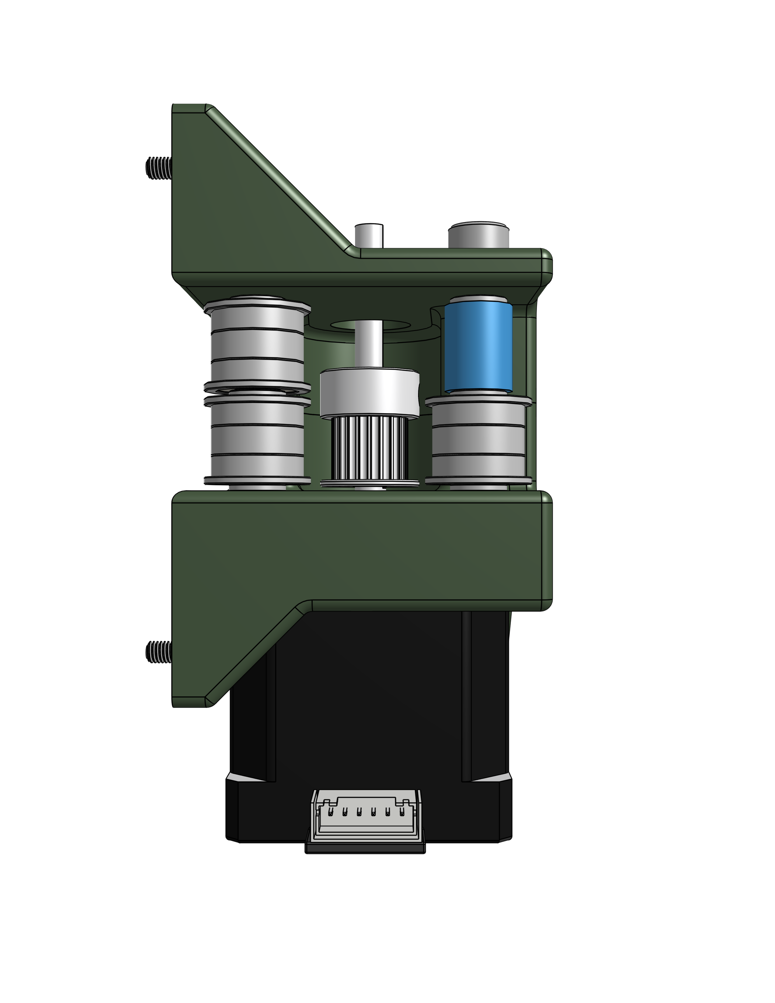
I used a CNC .25” aluminum plate to mount the moving part of the gantry to the Y axis linear rails. These mounts also held the idler pulleys to redirect the belt to the desired path. The belt path is shown below, with there being 2 belts - one per motor.
The belt tensioners were built into the belt path using an idler pulley and a pair of bolts that could tighten into heat set inserts to pull the belt tighter. This allows the belt to be put on loose and tightened down to the proper tension.
For the Z Axis, I used a triple zed leadscrew setup with custom kinematic mounts in order to allow for automatic bed leveling and bed flatness tests.
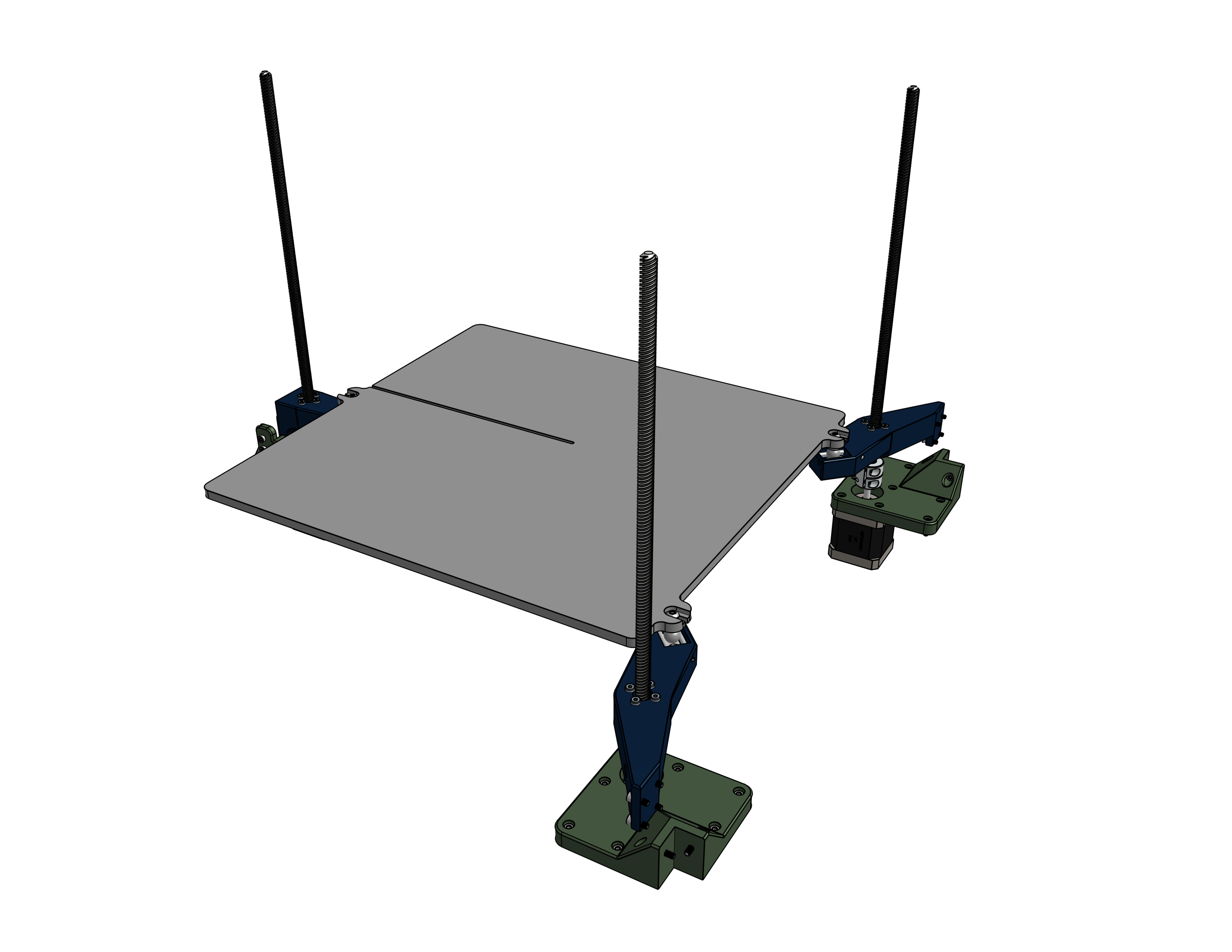
The kinematic mounts allow for the bed to remain flat as it expands and contracts due to the heat from the heated bed. The aluminum bed plate is bolted to three steel balls that rest on metal rods in the mount. There are magnets under these rods that are strong enough to contrain the steel balls to the rods, but still allow them to slide along the path those rods create.
Firmware
The firmware used on Hydra was a fork of Klipper called Kalico, formerly known as Danger Klipper. I made a custom profile and built out individual macros for each individual tool change and homing sequence, optomizing them to be as quick as possible while still having a perfect tool swap rate. The code can be found on the github.
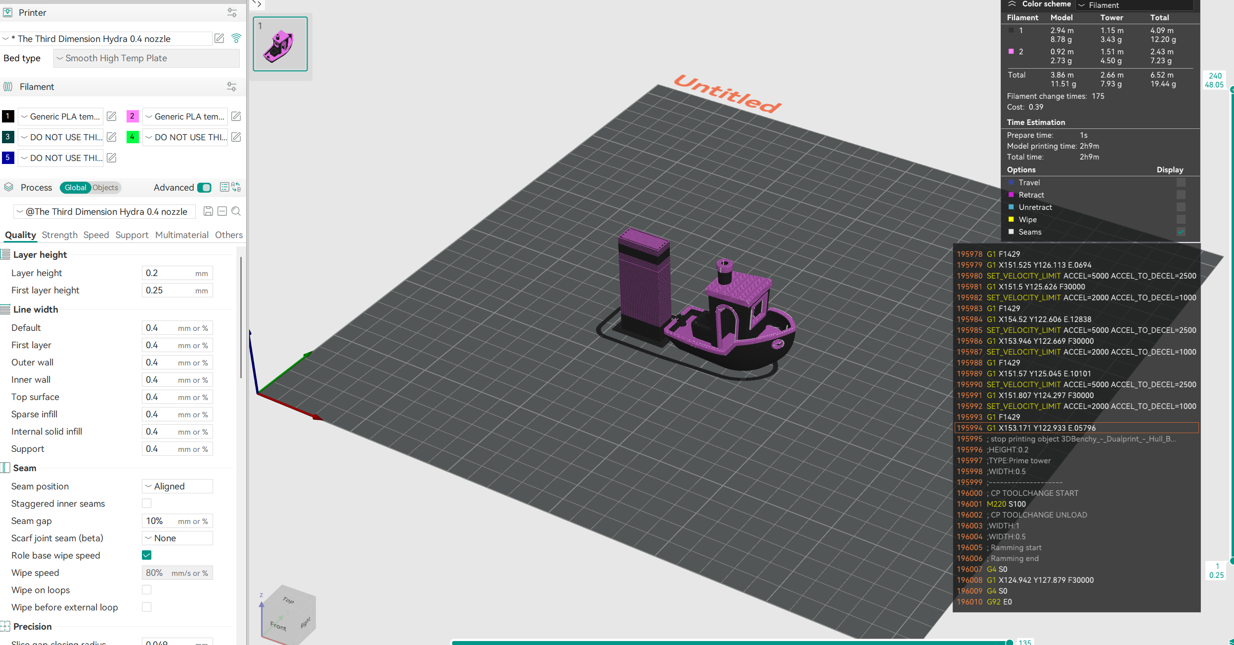
I also created and tuned a custom print profile on Orcaslicer, optomized for speed while still keeping print quality consistent. I also tuned in the purge tower in order to reduce the amount of filament waste that was created when printing in multiple colors. The slicer profile can be found on the github.
Final Results
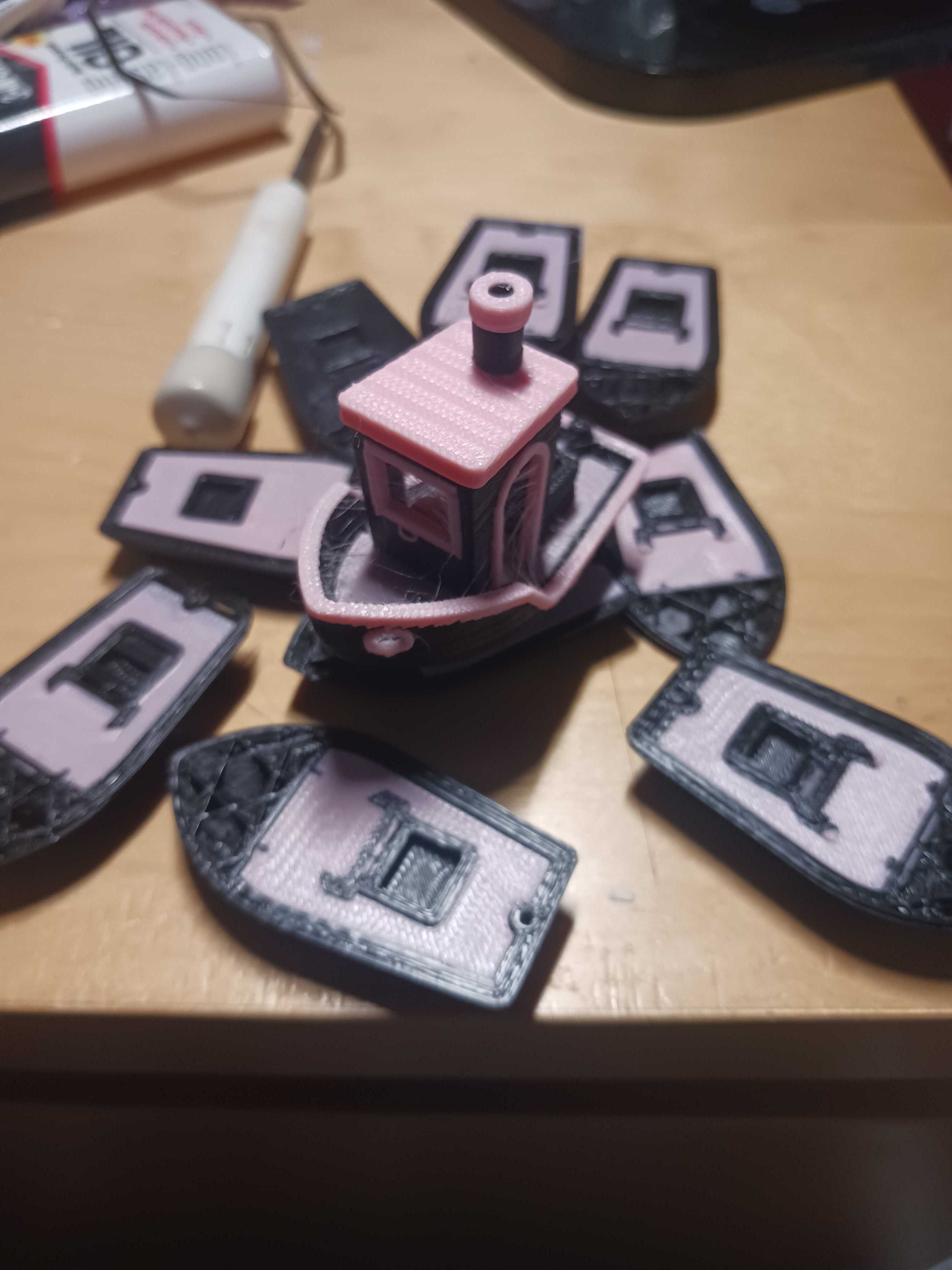
After assembling the entire printer, wiring it up, and troubleshooting many various problems with the wiring and firmware, Hydra was running smoothly. With my custom Orcaslicer profile, I could run some test multicolor prints, some of which are shown below.
After some tuning, I got a 2 color benchy!